The Engineering Guide to Powder Metallurgy Components Manufacturing
Powder metallurgy components are machined parts that are produced by compacting metal powders and sintering them at high temperatures. The process produces tight tolerances (±0.01mm), intricate geometries, as well as near-net-shape production with minimal waste of material. Commonly applied in the automotive, aerospace, and industrial industries, Powder metallurgy (PM) production comprises a low-cost substitute to machining and casting of large-volume, intricate part shapes.
Powder Metallurgy Components Guide Key Takeaways
| Parametr | Powder Metallurgy | Die Casting (Comparison) |
| Tolerancja wymiarów | ±0.01mm – ±0.05mm | ±0.05mm – ±0.1mm |
| Material Utilization | 95–97% | 85–92% |
| Ideal Production Volume | 10,000+ units/run | 5,000+ units/run |
| Common Materials | Iron, Copper, Stainless Steel, Bronze | Aluminum A380, ADC12, Zamak 3, Magnesium AZ91D |
| Opcje wykończenia powierzchni | Sintered, Plated, Impregnated | Anodizing, Malowanie proszkowe, Shot Blasting |
| Standardy jakości | ISO 9001, IATF 16949 | ISO 9001, IATF 16949 |
What Are Powder Metallurgy Components and How Are They Made?
Powder metallurgy (PM) is a net-shape or near-net-shape production method which transforms metallic powders into solid, functional components by way of compaction and sintering. As opposed to traditional methods of casting or machining, PM develops the piece by printing it at a microscopic scale from the ground at a microstructural level. This gives the engineer control over porosity, density, and alloy composition.
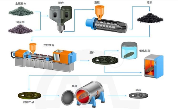
The typical PM manufacturing cycle has four fundamental stages:
Stage 1: Powder Preparation- Raw metal powders (iron, copper, nickel, stainless steel, bronze) are mixed with lubricants and alloying elements to attain the desired composition.
Stage 2:The blended powder is poured into a hardened die and compressed under pressures of between 150 and 900MPa to form a green compact that maintains its shape.
Stage 3: The green compact is heated in a controlled atmosphere furnace to 70-90% of the melting point of the metal. Atomic diffusion bonds the particles permanently without full melting.
Stage 4: Depending on what you need the parts for, they may undergo CNC Machining, sizing, heat treatment, plating, or oil impregnation to achieve the final specifications.
This sequence allows the manufacturing of powder metallurgy components having a wall thickness as low as 1.5mm, internal features and repeatable tolerances of ±0.01mm in large volume batches.
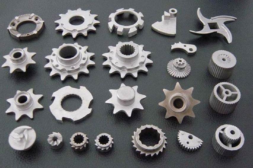
Why Are Powder Metallurgy Parts Critical for Automotive and Industrial Applications?
The automotive industry consumes over 70% of global PM. One of the major reasons for this is that powder metallurgy parts deliver mechanical performance, dimensional consistency, and production efficiency that few competing processes can match at scale.
PM is used in the production of self-lubricating bearings, structural brackets, valve seat inserts, and transmission components because the process allows controlled porosity. An example is the oil-impregnated sintered bearings. These components can operate without need for maintenance throughout the lifespan of a vehicle. This key performance characteristic is impossible to replicate through the casting process alone.
Key automotive applications include:
- Connecting rod caps and main bearing caps
- VVT (Variable Valve Timing) sprockets and rotors
- ABS sensor rings
- Transmission synchronizer hubs
- Oil pump gears and rotors
PM industrial applications include power tools, hydraulic systems, filtration components, and medical device housings. In short, anywhere that repeatable geometry and consistent density is an operational necessity.
For manufacturers who makes automotive parts that must meet IATF 16949 and ISO 9001 quality frameworks rely on PM’s process repeatability to achieve Cpk requirements and zero-defect delivery targets demanded by Tier 1 automotive suppliers. we are automotie die casting manufacturer in China, we are IATF 16946 certified die casting company in China.
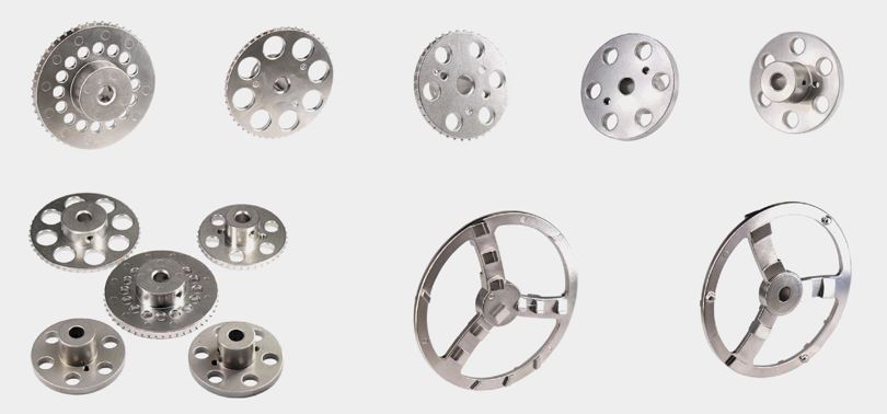
How Does Powder Metallurgy Gears Production Work, and What Tolerances Are Achievable?
Gears are one of the most challenging applications in PM manufacturing. Powder metallurgy gears production has improved greatly in the last 20 years, and gear manufacturers are now able to substitute broached or hobbed steel gears with sintered ones at a fraction of the unit price.
The Technical Case for Sintered Gears
Sintered gears are compacted directly to their final tooth profile geometry, eliminating the hobbing, shaping, and grinding operations that are required for cut steel gears. This reduces lead time by 30-50% and material scrap to under 3%.
PM gears can be achieved to standard specifications, which include:
- Module range: 0.5 to 6
- Tooth profile tolerance: DIN 8 to DIN 10 (AGMA Class 8–10)
- Bore tolerance: ±0.01mm with sizing operation
- Gęstość: 6.8–7.4 g/cm³ (iron-based)
- Tensile strength: Up to 900 MPa with sinter-hardening
Warm compaction or powder forging processes can be used to push density above 7.5 g/cm³ which are required for higher-load applications. This brings the mechanical properties close to wrought steel and helps retain the PM’s geometric flexibility.
Secondary Finishing for Gear Applications
Once sintered, gears that are to be used in high-load transmissions are usually subjected to:
- CNC gear grinding with precision of tooth profile to DIN 67.
- Surface hardness 58-62 HRC. Case hardening or induction hardening.
- Steam treatment or Powder Coating to give the corrosion resistance needed in the exposed environment.
For CNM Tech, the available in-house CNC machining can also enable the post-sinter finishing to be done within the same supply chain so that handling, lead time, and dimensional risks due to multiple vendor hand-offs are minimised.
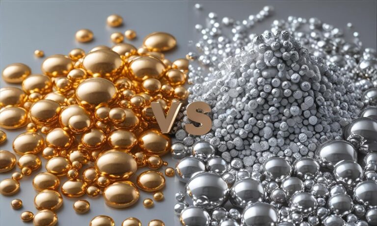
Powder Metallurgy vs. Die Casting: Which Process Is Right for Your Part?
Both die casting and PM are net-shape manufacturing processes of high volume, and are used in different design needs. It is a choice between geometry, material, mechanical load and volume of production.
Process Comparison
Powder Metallurgy — Advantages:
- Near-net-shape manufacturing using minimal secondary machining.
- Excellent dimensional repetitive capability at ±0.01mm.
- Self-lubrication, filtration Controlled porosity.
- Material flexibility: iron, copper, stainless steel, bronze, and mixed alloys.
- Reduced waste of materials (95-97% utilization of materials)
Powder Metallurgy — Limitations:
- Part size was usually less than 2.5 kg.
- Reduced ductility compared with equivalent density wrought or cast equivalents.
- Investment in complex 3D geometries is more expensive in tooling.
Die Casting — Advantages:
- It is good with thin-wall, complicated external geometries.
- Large selection of alloys: Aluminum A380, ADC12, Zamak 3, Magnesium AZ91D
- Good production rates (zinc alloys: 150 shots/hour)
- Excellent finish on the surface that is Anodizing and Powder Coating.
- Efficient with components that weigh over 2.5 kg and have big projections.
Die Casting — Limitations:
- Risk of porosity in unvacuum-assisted casting structural sections.
- Not as fit for those who needed controlled internal porosity.
- Increased tool expenses in low-volume batches.
The Bottom Line
If your part is a structural gear, bearing, or small precision component under 2.5 kg requiring tight bore tolerances and high-volume repeatability, powder metallurgy parts are the technically correct choice.
Die casting is the better way to go in case your component needs thin walls, large external surfaces, lightweight enclosures, or decorative finishes in aluminium or zinc alloy.
Most complex assemblies enjoy the advantages of both procedures, such as die-cast Aluminum A380 housing combined with sintered PM gears and bearings. The full service of CNM Tech encompasses both processes under one project management system, and, therefore, procurement teams find it easier to coordinate with the vendors.
What Quality Standards Govern Powder Metallurgy Components Manufacturing?
The concept of quality assurance in PM manufacturing is not a choice, but the basis of all repeatable production runs in engineering.
All powder metallurgy components, in CNM Tech, are manufactured and defined according to the quality management system of ISO 9001:2015 oraz IATF 16949:2016. These frameworks govern:
- Certification and traceability of powder of ingots coming in.
- Compact, force and density monitoring of the press.
- Sintering atmosphere control (dew point, temperature)
- Check of tolerances of less than 0.01mm using dimensional inspection with CMM (Coordinate Measuring Machine) inspection.
- Per production lot tests Hardness (Rockwell/Vickers)
- Cpk monitoring through statistical Process Control (SPC).
Components that are shipped to automotive Tier 1 buyers have complete PPAP (Production Part Approval Process) reports that contain material certifications, capability studies, and control plans.
Surface treatment processes, such as Malowanie proszkowe, electroless nickel plating and steam blackening, are also done to traceable specifications and the thickness of any coating is checked by XRF.
The CNM Tech Manufacturing Advantage
CNM Tech is a company with more than 20 years of precision manufacturing experience in China and is involved in the automotive, industrial, and consumer electronics sectors in North America, Europe, and Asia-Pacific.
Integrated Engineering Support
CNM Tech uses mold-flow analysis oraz compaction simulation to ensure the part geometry, density distribution and ejection are feasible before any tooling is cut by the engineering team. This front-end DFM (Design for Manufacturing) process can save money on tooling tricks and time-to-production can be saved by an average of 3-5 weeks.
Full-Service Supply Chain
CNM Tech is also in charge of the entire manufacturing process in-house:
- Design and fabrication of tools: compaction dies, core rods and punches.
- PM manufacture: blending, compaction and sintering.
- CNC machining: post-sinter size, drilling, threading, and gear grinding.
- Surface treatment: Powder Coating, plating, adjacent-anodising finishes,
- Quality and PPAP documentation: complete traceability of powder batch to finished part.
- Logistics and export compliance: direct shipment to customer DDP/DDU conditions.
This combined approach eradicates the discontinuous supplier paths that cause dimensional variance and delivery danger when PM production, machining and completing are distributed among three or four suppliers.
Powder Metallurgy Components Frequently Asked Questions
1. What is the minimum production volume that justifies powder metallurgy tooling investment?
At 10,000 and above parts per run of production, PM tooling is cost-effective. To find out the most cost-effective process (between 2,000 and 10,000 pieces), CNM Tech will use the engineering department to carry out a cost-per-part evaluation of PM versus CNC machining or die casting. Depending on the complexity of the parts, tooling expenses cost between 3000 and 15000 USD on average.
2. What dimensional tolerances can be held on sintered powder metallurgy parts without CNC secondary operations?
The as-sintered tolerances commonly are of the form ± 0.05mm on the outer diameters and the form 0.1mm on lengths. Bore and outer diameter tolerances after a sizing (re-pressing) process are better, at 0.01mm. The in-press features which cannot be made, like, undercuts and cross-holes, or threads, have to be CNC machined as a secondary process.
3. Can powder metallurgy gears production meet AGMA or DIN quality classes required for automotive transmission applications?
Yes. As-sintered gears normally reach DIN 9 -10 or AGMA Class 7 – 8. One can attain DIN 6 – 7 (AGMA Class 10 – 11) after CNC gear grinding. CNM Tech suggests the use of sinter-hardened or case-hardened PM gears to be followed by profile grinding in high-load transmission applications to obtain the desired accuracy in the tooth and contact fatigue behaviour.
4. What alloy systems are available for powder metallurgy parts, and how do they compare to die casting alloys like Aluminum A380 or Zamak 3?
PM alloys are mainly iron (Fe-Cu-C, Fe-Ni-Mo), copper-based or stainless steel (316L, 410). These are radically different to die casting alloys such as Aluminum A380, ADC12, or Zamak 3, which are melted. The choice of PM alloys is determined by magnetic properties, wear resistance and controlled porosity rather than the thin-wall castability and decorative finish of aluminum and zinc alloys of die casting.
5. How does CNM Tech ensure IATF 16949 compliance for powder metallurgy components supplied to automotive Tier 1 customers?
The quality management system of CNM Tech is ISO 9001: 2015 and IATF 16949:2016 certified. Automotive PM components have been manufactured with complete PPAP documentation (Level 1-5 as needed), i.e. material certifications, MSA studies, dimensional layout report and approved control plan. SPC control is used over important attributes in the production process, and the non-conformance is followed and reported by using a process of 8D corrective action.
Ready to Source Precision Powder Metallurgy Components?
In case you are considering powder metallurgy parts in the next program – be it automotive gears, structural bracket, or even customer sintered components CNM Tech engineering team is willing to look into it and develop a comprehensive DFM analysis without any charge.
Submit your 3D part design in either STP or IGS format and requirements. Our group will reply to you in 24 hours with an approximate report on DFM, selections of alloys and processes, and a competitive unit price proposal depending on your intended volume. You need 10,000 or 5,000,000 pieces annually; either way, you will get the required accuracy and dependability of your program with the help of the integrated supply chain offered by CNM Tech, starting with the design of the tool and finishing with its inspection.