What Is Investment Casting?
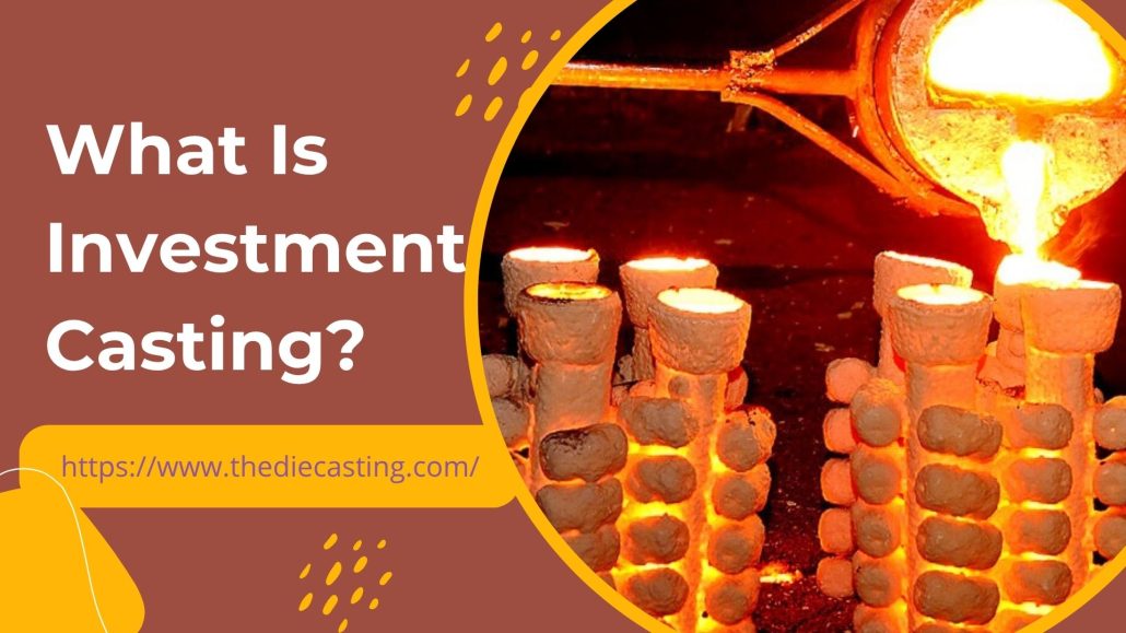
alümi̇nyum dökümInvestment casting is a highly precise production method used to make complex metal parts with high dimensional accuracy and surface finish. The process entails carving a wax figure of the required component, applying a ceramic shell to the figure, then using epoxy on the wax, and finally pouring heated metal into the figure, which has been left hollow. The technique is also commonly referred to as lost-wax casting because the wax pattern is melted away during the process. The technique is appreciated in various industries, where it can produce complex shapes, thin-walled, and detailed geometries that cannot be easily produced by most other casting methods. The resulting parts are usually near-net shape, meaning they require little machine work or additional after-cast processing. This allows manufacturers to save on material waste and production time while maintaining high precision. The history of investment casting dates back thousands of years. The process was used to produce jewelry, ornaments, and sculptures by ancient civilizations. Gradually, the method evolved into an indispensable part of industrial production. Industries, including aerospace, automotive, medical devices, industrial machinery, and energy systems, now use investment casting. Investment Casting Overview Investment casting is an investment process that involves creating and executing an investment plan created by a company’s owners or managers. Investment casting, in simple terms, is the process of enclosing a wax pattern in a ceramic mold. As soon as the ceramic shell has hardened, the wax is melted out, leaving an opening that perfectly reproduces the original pattern. This cavity is then filled with molten metal, which hardens, and the ceramic shell is chipped off to expose the final piece of metal. The process can manufacture parts with: The history of Investment Casting Investment casting is more than 5000 years old. Archaeological records indicate that ancient cultures had the process of producing jewelry, tools, and decorative objects. Early versions of the lost-wax casting technique were used in civilizations such as the Egyptian, Chinese, and Mesopotamian, as well as the Indus Valley societies. In ancient Egypt, the process was used to make detailed pieces of gold jewelry and ceremonial artifacts. On the same note, Chinese artisans employed it in the production of bronze sculptures and ritual vessels. The fundamental principles of the process have not been changed significantly over the centuries. With the Industrial Revolution and the rise of modern manufacturing, investment casting became a highly advanced and highly restrictive process. The technique has been made more precise, efficient, and scalable through developments in materials science, engineering, and computer-aided design (CAD). Modern investment casting combines traditional concepts with modern technologies, including 3D printing, automation, and computer simulation. Investment Casting Principle of Work Investment casting works on the principle of making a sacrificial pattern, which is an embodiment of the final product. This pattern is coated with a refractory material to create a mold that withstands high temperatures. The final part is made by pouring molten metal into the cavity after the wax pattern has been removed. All the details of the wax pattern are captured by the ceramic mold, making it very accurate at reproducing even complex shapes. The process can produce elaborate internal cavities and thin walls, as the wax is removed before the addition of metal, unlike other casting methods, which are constrained by these limitations. Another important aspect of investment casting is that the mold is destroyed during the process. The ceramic shell mold is not reused, as is the case with reusable molds used in die casting, but is broken away after the metal solidifies. This gives the freedom to design more and the possibility to manufacture parts with complex geometries. Investment Casting Process in Steps The process can vary slightly by manufacturer and material, but, in general, the investment casting process has several major steps. Pattern Creation The first step is to create a pattern that mimics the end product. This trend is usually created in wax, but plastic or other substances are sometimes used. The wax pattern is typically made by pouring the melted wax into a part-specific metal mold. Trends can also be created through 3D printing technologies in contemporary manufacturing, enabling quick prototyping and design alterations. Assembly of Wax Patterns Multiple patterns on wax are often placed on a central sprue to create a wax tree or cluster. This design allows casting many parts in a single mold, enhancing production efficiency. Sprue systems are also used to convey molten metal during the casting process. Ceramic Shell Formation One dips the wax assembly in a slurry of ceramic and covers it with fine sand or refractory particles. The procedure is repeated several times to form a stiff ceramic shell around the wax mold. One layer has to dry, and then the other is laid. The shell becomes thick and hard enough to withstand the high temperatures and pressure of molten metal after several coatings. Dewaxing After the ceramic shell fully hardens, the wax is removed by heating the mold. This is usually done in an autoclave or by fire. Heat melts and drains the wax from the shell, forming a hollow cavity that accurately fits the shape of the pattern. Since this step involves removing the wax, the procedure is known as lost-wax casting. Preheating the Mold The ceramic shell is heated in a furnace before the metal is poured into the mold, removing moisture and strengthening the shell. Preheating is also used to ensure that the molten metal flows freely in the cavity without freezing. Pouring the Molten Metal The sprue system is used to pour molten metal into the preheated mold. The cavity is filled with metal, which takes on the exact shape of the wax pattern. Depending on the application and the required material properties, different metals and alloys may be used. Cooling and Solidification Once this is poured, the metal is left to cool and harden in the ceramic mold. Some factors that determine the cooling time include the metal used, the part size, and the mold temperature.